555 Timer Internal Schematic / Quick 555 timer astable multivibrator mode circuit ... - There are a lot of applications of this ic, mostly used as vibrators like, astable multivibrator, monostable multivibrator, and bistable multivibrator.
555 Timer Internal Schematic / Quick 555 timer astable multivibrator mode circuit ... - There are a lot of applications of this ic, mostly used as vibrators like, astable multivibrator, monostable multivibrator, and bistable multivibrator.. The standard timer action of the ic 555 is initiated by introducing a 0 v trigger pulse at pin 2. How it works, internal schematic and block diagram. In astable mode, the output cycles on and off continuously. File c555 internal circuitg wikimedia mons from 555 timer internal schematic , source:commons.wikimedia.org 1 minute 5 minute 10 thanks for visiting our site, articleabove (555 timer internal schematic unique) published by at. The 555 timer ic was first introduced around 1971 by the signetics corporation as the se555/ne555 and was.
The 555 timer has two basic operational modes: The schematic is designed in kicad. The image shown below represents the internal schematic of a standard ic 555. Usually used to create time delays. File c555 internal circuitg wikimedia mons from 555 timer internal schematic , source:commons.wikimedia.org 1 minute 5 minute 10 thanks for visiting our site, articleabove (555 timer internal schematic unique) published by at.
555 timer IC — Wikipedia Republished // WIKI 2 from upload.wikimedia.org Refer to the internal 555 schematic of fig. The 555 timer has two basic operational modes: Resistor r1 is connected between vcc and the discharge pin (pin 7) and another resistor (r2) is connected between the discharge pin (pin 7). My goal was to research some about them then design my own circuit. [node:summary555 timer ic is one of the commonly used ic among students and hobbyists. As shown in figure 12, the external capacitor is typical schematics in monostable operation. We can see that it us made up of 21 transistors, 4 diodes, and 15 resistors. Lm555 timer internal circuit block diagram.
In this article, we will cover about 555 timers.
555 internal schematic of bipolar version. (1) for all available packages, see the orderable addendum at the end of the datasheet. Learn about the 555 timer and how it works in astable mode. This 0v pulse being below the 1/3rd level of the dc. Lm555 timer internal circuit block diagram. The 555 timer can operate in three different modes: The internal resistors act as a voltage divider. The circuit latches in either the q state or its refer block diagram of 555 timer ic given above: With this information you will learn how how the 555 works and will have the experience to build some of the circuits below. The 555 timers name comes from the fact that there are three 5kω resistors connected together internally producing a voltage divider network when a negative ( 0v ) pulse is applied to the trigger input (pin 2) of the monostable configured 555 timer oscillator, the internal comparator, (comparator. [node:summary555 timer ic is one of the commonly used ic among students and hobbyists. The 555 timer ic is an integrated circuit (chip) used in a variety of timer, delay, pulse generation, and oscillator applications. Here's the internal schematics of 555 timer which consists of 25 transistors, 2 diodes and 15 resistors.
Now a days it is manufactured by many companies in bipolar and in low power cmos. The files are available for download at the end of the page. File c555 internal circuitg wikimedia mons from 555 timer internal schematic , source:commons.wikimedia.org 1 minute 5 minute 10 thanks for visiting our site, articleabove (555 timer internal schematic unique) published by at. Well here are a couple of schematics from the national semiconductor datasheet to a large amount of my time and research was spent on the comparators. Finally, power up your circuit by connecting the battery to.
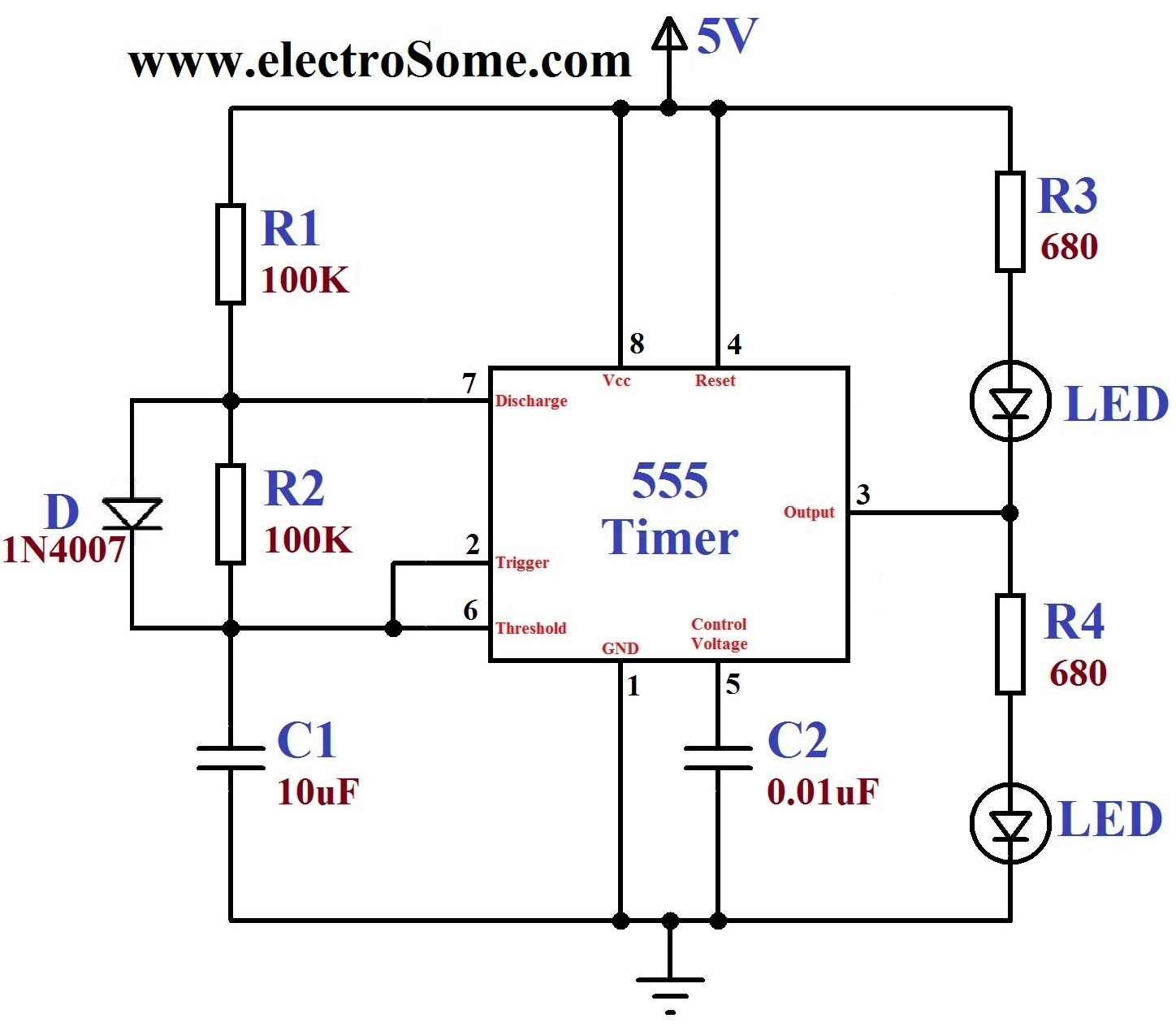
Dancing Light using 555 Timer from electrosome.com The 555 timer was introduced over 40 years ago. Schematic of a 555 timer in oscillator mode. The 555 timer ic was first introduced around 1971 by the signetics corporation as the se555/ne555 and was. The schematic is designed in kicad. How it works, internal schematic and block diagram. Today we're pleased to declare that we have. Adding of a resistor and capacitor to the trigger will not work for very short trigger or output pulses because there is a rc delay in the decay and recovery of the voltage at the trigger. Let's take a closer look what's inside the 555 timer and explain how it works in each of the three modes.
So what the heck is going on inside the 555 timer?
Refer to the internal 555 schematic of fig. The circuit latches in either the q state or its refer block diagram of 555 timer ic given above: (1) for all available packages, see the orderable addendum at the end of the datasheet. Lm555 timer internal circuit block diagram. So what the heck is going on inside the 555 timer? My goal was to research some about them then design my own circuit. There are a lot of applications of this ic, mostly used as vibrators like, astable multivibrator, monostable multivibrator, and bistable multivibrator. The schematic is designed in kicad. In astable mode, the 555 timer puts out a continuous stream of rectangular pulses having a specified frequency. The 555 timer ic was first introduced around 1971 by the signetics corporation as the se555/ne555 and was. As shown in figure 12, the external capacitor is typical schematics in monostable operation. Built the one in the schematic and it worked briefly but the 555 timer ic chip kept getting fried because it was being forced to sink more than 400 ma or more so im trying to construct an oscillator by changing the internal components so i can related threads on 555 timer internal schematic questions. The 555 timer ic is an integrated circuit (chip) used in a variety of timer, delay, pulse generation, and oscillator applications.
The files are available for download at the end of the page. Derivatives provide two (556) or four (558) timing circuits in one package. With this information you will learn how how the 555 works and will have the experience to build some of the circuits below. Look at the circuit diagram. The 555 timer ic is an integrated circuit (chip) used in a variety of timer, delay, pulse generation, and oscillator applications.
Astable Multivibrator using 555 Timer from www.circuitstoday.com 555 internal schematic of bipolar version. Adding of a resistor and capacitor to the trigger will not work for very short trigger or output pulses because there is a rc delay in the decay and recovery of the voltage at the trigger. Well here are a couple of schematics from the national semiconductor datasheet to a large amount of my time and research was spent on the comparators. The 555 timer can operate in three different modes: The circuit latches in either the q state or its refer block diagram of 555 timer ic given above: The schematic is designed in kicad. Here's the internal schematics of 555 timer which consists of 25 transistors, 2 diodes and 15 resistors. Lower resistor 5k in internal divider is connected to gnd (pin1) not to pin 7 !!!!
File c555 internal circuitg wikimedia mons from 555 timer internal schematic , source:commons.wikimedia.org 1 minute 5 minute 10 thanks for visiting our site, articleabove (555 timer internal schematic unique) published by at.
Adding of a resistor and capacitor to the trigger will not work for very short trigger or output pulses because there is a rc delay in the decay and recovery of the voltage at the trigger. The 555 timer is a simple integrated circuit that can be used to make many different electronic circuits. In the monostable mode, the timer generates a single pulse. There are a lot of applications of this ic, mostly used as vibrators like, astable multivibrator, monostable multivibrator, and bistable multivibrator. The 555 timer ic was first introduced around 1971 by the signetics corporation as the se555/ne555 and was. Here we describe how to configure a standard 555 ic to perform two of its most common functions. Refer to the internal 555 schematic of fig. 555 timer ic internal schematic. This circuit uses the 555 timer in an astable operating mode which generates a continuous output via pin 3 in the form of a square wave. File c555 internal circuitg wikimedia mons from 555 timer internal schematic , source:commons.wikimedia.org 1 minute 5 minute 10 thanks for visiting our site, articleabove (555 timer internal schematic unique) published by at. Let's take a closer look what's inside the 555 timer and explain how it works in each of the three modes. Refer to the internal 555 schematic of fig. This integrated circuit can be used in a variety of ways from which the basic one is to produce accurate and stable delays in electronic circuits.
Outputs an oscillating pulse you can either follow the previous schematic or follow the breadboard wiring diagram below 555 timer schematic. There are a lot of applications of this ic, mostly used as vibrators like, astable multivibrator, monostable multivibrator, and bistable multivibrator.


0 Komentar