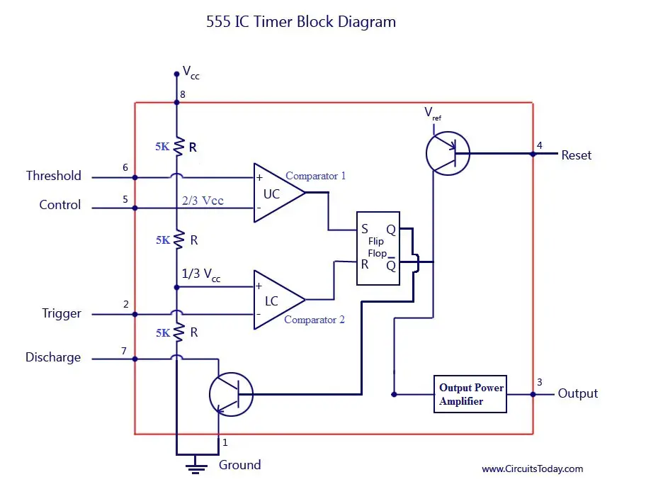
555 Timer Schematic Symbol - The Three Fives Kit: A Discrete 555 Timer - RF Cafe - The internal block diagram and schematic of the 555 timer are highlighted with the same color across all three drawings to clarify how the chip is implemented:
555 Timer Schematic Symbol - The Three Fives Kit: A Discrete 555 Timer - RF Cafe - The internal block diagram and schematic of the 555 timer are highlighted with the same color across all three drawings to clarify how the chip is implemented:. For example, you might put a transistor on the output pin of a 555 timer ic (which produces a variable timing pulse), or a shift register ic (which allows you to produce multiple control signals in parallel) to control high current loads from those devices. We need to set 555 timer in monostable mode to build timer. So to build 1 minute (60 seconds) timer we need resistor of value 55k ohm and capacitor of 1000uf: Frank silavwe on bc547 transistor project Between the positive supply voltage v cc and the ground gnd is a voltage divider consisting of three identical resistors, which create two reference voltages at 1 ⁄ 3 v cc and 2.
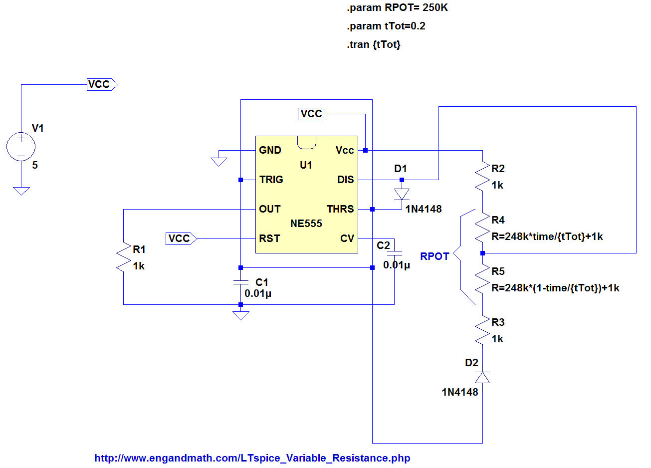
These tools allow students, hobbyists, and professional engineers to design and analyze analog and digital systems before ever building a prototype. Jul 14, 2015 · all we need to change the value of resistor r1 and/or capacitor c1. Frank silavwe on bc547 transistor project Between the positive supply voltage v cc and the ground gnd is a voltage divider consisting of three identical resistors, which create two reference voltages at 1 ⁄ 3 v cc and 2. Nand gate conversion & example.
555 Timer IC | Electronics Club from electronicsclub.info The editor is fairly straightforward and has tons of hotkeys associated with it to make it easy when creating a component with several pins. If we don't know the symbols of the schematic circuit, it is extremely hard to create a project. In monostable mode, the duration for which the pin 3 would remain high, is given by the below formulae: Here this article discusses most of the circuit symbols of electronic components and their functions. For example, you might put a transistor on the output pin of a 555 timer ic (which produces a variable timing pulse), or a shift register ic (which allows you to produce multiple control signals in parallel) to control high current loads from those devices. We need to set 555 timer in monostable mode to build timer. The internal block diagram and schematic of the 555 timer are highlighted with the same color across all three drawings to clarify how the chip is implemented: Nand gate conversion & example.
If we don't know the symbols of the schematic circuit, it is extremely hard to create a project.
Nand gate schematic of above function is given below. We need to set 555 timer in monostable mode to build timer. In monostable mode, the duration for which the pin 3 would remain high, is given by the below formulae: T = 1.1 * r1*c1. If we don't know the symbols of the schematic circuit, it is extremely hard to create a project. Frank silavwe on bc547 transistor project Same as adding the schematic, just add a schlib to the project and watch it fall underneath "libraries" inside your project. Between the positive supply voltage v cc and the ground gnd is a voltage divider consisting of three identical resistors, which create two reference voltages at 1 ⁄ 3 v cc and 2. Nand gate conversion & example. These tools allow students, hobbyists, and professional engineers to design and analyze analog and digital systems before ever building a prototype. There is no 555 timer though, so let's create our own. So to build 1 minute (60 seconds) timer we need resistor of value 55k ohm and capacitor of 1000uf: Jul 14, 2015 · all we need to change the value of resistor r1 and/or capacitor c1.
In monostable mode, the duration for which the pin 3 would remain high, is given by the below formulae: The internal block diagram and schematic of the 555 timer are highlighted with the same color across all three drawings to clarify how the chip is implemented: So to build 1 minute (60 seconds) timer we need resistor of value 55k ohm and capacitor of 1000uf: These tools allow students, hobbyists, and professional engineers to design and analyze analog and digital systems before ever building a prototype. There is no 555 timer though, so let's create our own.
Astable Multivibrator using 555 Timer from www.circuitstoday.com For example, you might put a transistor on the output pin of a 555 timer ic (which produces a variable timing pulse), or a shift register ic (which allows you to produce multiple control signals in parallel) to control high current loads from those devices. Frank silavwe on bc547 transistor project We need to set 555 timer in monostable mode to build timer. Between the positive supply voltage v cc and the ground gnd is a voltage divider consisting of three identical resistors, which create two reference voltages at 1 ⁄ 3 v cc and 2. In monostable mode, the duration for which the pin 3 would remain high, is given by the below formulae: Jul 14, 2015 · all we need to change the value of resistor r1 and/or capacitor c1. Nand gate conversion & example. The editor is fairly straightforward and has tons of hotkeys associated with it to make it easy when creating a component with several pins.
Here this article discusses most of the circuit symbols of electronic components and their functions.
Nand gate schematic of above function is given below. Nand gate conversion & example. Jul 14, 2015 · all we need to change the value of resistor r1 and/or capacitor c1. If we don't know the symbols of the schematic circuit, it is extremely hard to create a project. These tools allow students, hobbyists, and professional engineers to design and analyze analog and digital systems before ever building a prototype. Same as adding the schematic, just add a schlib to the project and watch it fall underneath "libraries" inside your project. We need to set 555 timer in monostable mode to build timer. The editor is fairly straightforward and has tons of hotkeys associated with it to make it easy when creating a component with several pins. T = 1.1 * r1*c1. Frank silavwe on bc547 transistor project Electronic symbols are very essential to know while designing circuits for a project or while making a pcb for a project. In monostable mode, the duration for which the pin 3 would remain high, is given by the below formulae: There is no 555 timer though, so let's create our own.
Jul 14, 2015 · all we need to change the value of resistor r1 and/or capacitor c1. So to build 1 minute (60 seconds) timer we need resistor of value 55k ohm and capacitor of 1000uf: For example, you might put a transistor on the output pin of a 555 timer ic (which produces a variable timing pulse), or a shift register ic (which allows you to produce multiple control signals in parallel) to control high current loads from those devices. Frank silavwe on bc547 transistor project Nand gate conversion & example.
Analysis of 555-Based PWM Circuit | Math Encounters Blog from i0.wp.com Nand gate schematic of above function is given below. Same as adding the schematic, just add a schlib to the project and watch it fall underneath "libraries" inside your project. So to build 1 minute (60 seconds) timer we need resistor of value 55k ohm and capacitor of 1000uf: The editor is fairly straightforward and has tons of hotkeys associated with it to make it easy when creating a component with several pins. Electronic symbols are very essential to know while designing circuits for a project or while making a pcb for a project. Here this article discusses most of the circuit symbols of electronic components and their functions. Nand gate conversion & example. Jul 14, 2015 · all we need to change the value of resistor r1 and/or capacitor c1.
Nand gate conversion & example.
The editor is fairly straightforward and has tons of hotkeys associated with it to make it easy when creating a component with several pins. The internal block diagram and schematic of the 555 timer are highlighted with the same color across all three drawings to clarify how the chip is implemented: For example, you might put a transistor on the output pin of a 555 timer ic (which produces a variable timing pulse), or a shift register ic (which allows you to produce multiple control signals in parallel) to control high current loads from those devices. Same as adding the schematic, just add a schlib to the project and watch it fall underneath "libraries" inside your project. If we don't know the symbols of the schematic circuit, it is extremely hard to create a project. Nand gate schematic of above function is given below. Frank silavwe on bc547 transistor project Jul 14, 2015 · all we need to change the value of resistor r1 and/or capacitor c1. Here this article discusses most of the circuit symbols of electronic components and their functions. There is no 555 timer though, so let's create our own. Between the positive supply voltage v cc and the ground gnd is a voltage divider consisting of three identical resistors, which create two reference voltages at 1 ⁄ 3 v cc and 2. In monostable mode, the duration for which the pin 3 would remain high, is given by the below formulae: We need to set 555 timer in monostable mode to build timer.
These tools allow students, hobbyists, and professional engineers to design and analyze analog and digital systems before ever building a prototype 555 timer schematic. Between the positive supply voltage v cc and the ground gnd is a voltage divider consisting of three identical resistors, which create two reference voltages at 1 ⁄ 3 v cc and 2.


0 Komentar